NDS Supplement Tables 1A–6B: The Comprehensive Practical Guide for Wood Design
This is a long-form, practice-oriented guide to navigating the NDS Supplement (Series 1, 4, 5, and 6) for wood design in the United States: dimension lumber, timbers, structural decking, imported species, multi-species groups, glued laminated timber (glulam), and round timber (piles and poles). It is written for structural engineers, PE exam review, plan check preparation, and technical SEO discovery (search terms such as NDS Supplement 2024, reference design values, F_b F_v E E_min, Table 4A, Table 5A stress class, MSR MEL, glulam 24F-1.8E). For in-app species/size selection and adjustment factors, use the Wood Beam and Wood Column modules (/design/wood-beam, /design/wood-column); this note remains the reference for table meaning and footnotes.
Core idea: Successful wood design separates geometry (what size is the member, and what are A, S, I?) from capacity (what are the reference design values for that species and grade?). The Supplement holds the tabulated reference values; the NDS Specification tells you how to apply adjustment factors to obtain adjusted capacities.
- Reference design values (F_b, F_v, F_c, F_t, F_c⊥, E, E_min, etc.) come from the Supplement tables.
- Adjusted design values (F′b, F′v, F′c, etc.) result after C_D, C_M, C_t, C_F, C_L, C_P, and other factors from the NDS Specification.
Big picture: three layers (geometry, strength, design)
| Layer | Question | Where to look |
|---|---|---|
| 1 — Geometry | Nominal vs dressed size; A, S, I; glulam width/depth | 1A, 1B, 1C, 1D |
| 2 — Material strength | Reference stresses and moduli for the species/grade/stress class | 4A–4G (sawn), 5A–5D (glulam), 6A–6B (round) |
| 3 — Design | Combine properties with NDS equations; compare demand to adjusted capacity | NDS Specification Chapters 3–4 (and project criteria) |
Memory shortcut: 1 = geometry · 4 or 5 = strength (solid sawn vs glulam) · NDS = equations and adjustment factors.
Cross-section dimensions and axes (NDS Supplement)
The NDS Supplement defines rectangular member geometry the same way for solid sawn sections and structural glued laminated timber: b is the width, d is the depth, and centroidal axes X-X and Y-Y identify strong-axis vs weak-axis bending for properties such as S_x, I_x, S_y, and I_y in Tables 1B, 1C, and 1D. Laminations in glulam are shown parallel to X-X (horizontal layers in the standard figure).
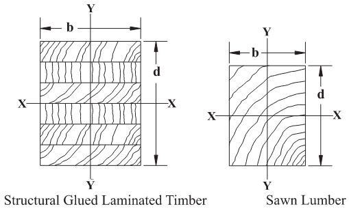
Figure: NDS Supplement, Dimensions for rectangular cross section (glulam vs sawn lumber). Use this nomenclature when reading A, S, and I and when orienting loads relative to X-X / Y-Y.
Part 1 — Sawn lumber basics (Tables 1A, 1B)
Sawn lumber vs S4S
- Sawn lumber is the general term for wood cut from logs and used in structures.
- S4S (surfaced four sides) means the piece was planed smooth on all four faces at the mill. In modern construction, almost all off-the-shelf dimension lumber is S4S. Planing reduces cross-section: the nominal label (e.g., 2×4) is not the actual dressed size (e.g., 1.5 in. × 3.5 in.).
Table 1A — nominal vs dressed sizes
Table 1A is the reference that ties nominal names to minimum dressed (actual) dimensions. Engineers use it whenever they must state or verify b and d explicitly.
Table 1B — section properties for analysis
Table 1B lists pre-calculated A, S, and I (and related properties) based on the dressed sizes that trace back to 1A. For beam-type calculations, 1B is the fast path: you read S for bending stress and I for deflection checks.
Why Table 1A still matters if Table 1B has properties
Table 1B is a compact “analysis package”: it gives A, S_x, I_x (and similar) without re-deriving geometry. Table 1A still matters because many design tasks require actual width and depth, not only S and I:
- Formulas that use b and d directly — Examples include shear stress proportional to V/(bd), bearing contact area tied to b (and bearing length), and other checks where the Supplement or NDS expects in-plane dimensions.
- Connection design — Bolts, nails, screws, and dowel-type fasteners use edge distance, end distance, spacing, and penetration rules that depend on actual member thickness and width. Table 1B does not replace those dimensional rules.
- Non-standard or built-up sections — Double joists (2–2×10), site-spliced members, or sizes not listed in 1B: get dressed sizes from 1A (or the fabricator) and compute A, S, I manually.
- Drawings and submittals — Construction documents usually call out nominal sizes; 1A converts nominal → actual for review, RFIs, and QA/QC.
- Bearing and bearing plates — Contact area and bearing stress checks often need actual width (and length) to define A_bearing.
Practical rule:
- Need S or I for member analysis → Table 1B (when the size is listed).
- Need b or d for mechanics, connections, or detailing → Table 1A.
Think of 1B as pre-calculated analysis properties and 1A as real cross-section geometry for everything that is not a simple M/S or EI flexure check.
Member classifications (Table 1B context)
- Boards: Less than 2 in. nominal thickness.
- Dimension lumber: 2 in.–4 in. thick (typical 2×, 4× framing).
- Timbers: 5 in. × 5 in. and larger.
- Beams and stringers (B&S): Width more than 2 in. greater than thickness—used for flexural grading in the timber regime (4D).
Part 2 — Glulam geometry (Tables 1C and 1D)
Why Western vs Southern tables (and where Douglas Fir sits)
Glulam is manufactured from regional species and supply chains. Douglas Fir (DF) and other Western species are covered under Table 1C. Southern Pine is handled in Table 1D because standard widths, lamination thicknesses, and milling practices differ from Western production (for example, 1.375 in. laminations vs 1.5 in. in many Western layups—always read the Supplement for your exact row).
Radius of gyration r_y in Table 1C (constant width)
For a fixed width b, the radius of gyration about the weak axis, r_y, does not change when depth increases (more laminations). Weak-axis distribution of area relative to b is unchanged; only depth changes. That is why r_y can repeat across depths for a given width in glulam property listings.
Part 3 — Visual vs mechanical grading (Tables 4A–4D and related)
Definitions
- Visually graded lumber (Tables 4A, 4B, 4D, etc.): A human inspector or approved visual/automated system grades knots, grain slope, shake, and other defects. This is the default assumption for much field-framing and general construction when the spec says No. 2 or Select Structural without MSR/MEL.
- Mechanically graded lumber (Table 4C — MSR/MEL): Each piece is machine-tested (stiffness E or density-related methods) and assigned a machine grade. MSR (Machine Stress Rated) and MEL (Machine Evaluated Lumber) are common categories.
Specification habit
If a specification says “No. 2 DF-L” and does not call out MSR/MEL, the industry default is visually graded lumber unless the contract documents say otherwise.
Retail and procurement
Retail yards (including typical big-box inventory) almost exclusively stock visually graded lumber (No. 2, Prime, Stud, etc.). MSR/MEL is often special order for truss plants, engineered packages, or performance-critical jobs.
Which is “stronger” or “better”?
- Mechanical grading reduces variability and often yields predictable E and F_b for a given product line—valuable for trusses and fabricated assemblies.
- High visual grades (e.g., Select Structural) can still exceed lower mechanical grades on a piece-by-piece basis. Always design to the stamp and the correct table row.
Industry volume context (not code)
Mechanically graded lumber (MSR/MEL) is often cited as on the order of roughly 5–10% of total structural lumber volume in the U.S.—but metal-plate-connected wood trusses may use MSR for a very large share of their lumber (commonly roughly 70–80% in industry discussions). General residential framing (studs, joists) remains predominantly Visually Graded No. 2 (often cited roughly 85% in broad framing statistics). Treat these as market context; always verify project-specific specifications and grades on stamps.
Why visual grading still dominates overall volume
Cost (mill equipment), throughput (high-volume visual lines), and code familiarity (IBC/IRC tables and common specs centered on visual grades) all reinforce visual as the default for bulk construction.
Part 4 — Series 4 sawn lumber tables: what each one is for
Table 4A — Dimension lumber (general species)
Table 4A covers dimension lumber for species other than Southern Pine (e.g., Douglas Fir–Larch, Hem-Fir, Spruce-Pine-Fir per the Supplement). You must apply size factor C_F and other factors per NDS Chapter 4 and the Supplement headings—not double-count rules already embedded in a row.
Table 4B — Southern Pine
Southern Pine has different tabulation and size-dependent behavior. C_F is often already incorporated in 4B tabulated reference values—do not apply C_F again unless the Supplement explicitly directs you for your selected row.
Table 4C — Mechanically graded (MSR/MEL)
Mechanical grades emphasize predictable stiffness and stiffness-sorted strength—common in truss manufacturing and engineered applications. F_c⊥ (bearing perpendicular to grain) is fundamentally a species/section issue: for 4C, follow Supplement footnotes and species-appropriate sources (sometimes referencing visual tables for that species) to obtain F_c⊥.
Table 4D — Timbers (5 in. × 5 in. and larger)
Large rectangular sections: distinguish beams & stringers vs posts & timbers per grading rules and NDS usage. E and F_b footnotes can differ—read the row you select.
Table 4E — Structural decking
Table 4E is for heavy timber decking (e.g., 2–4 in. thick tongue-and-groove planks) in commercial floors/roofs—not a residential deck surface or railing member.
Table 4F — Non–North American species (imported lumber for U.S. design)
Table 4F supports imported lumber used to build in the United States when the Supplement lists the species/grade. It reflects foreign growth and grading rules that differ from domestic species. It is not a substitute for designing under another country’s building code when the project is outside the U.S.
Table 4G — Multi-species groups
Table 4G applies when lumber is sold and stamped as a group (e.g., SPF) where species may mix within a bundle. Tabulated values are a conservative “group” set so the member is safe regardless of which species in the group is actually pulled for that piece.
Footnote discipline
In Series 4, E and F_b can follow different footnotes in the same region of a table. Read the exact row and all applicable notes.
Part 5 — How the tables work together (geometry + capacity)
Grade ladder (typical strength ranking — confirm in Supplement)
For structural grades in 4A, higher grades generally mean fewer defects:
- Select Structural (SS) — highest tabulated strengths for the species group.
- No. 1 / No. 2 — common structural grades (No. 2 is extremely common in practice).
- No. 3 / Stud — lower strengths; Stud often associated with stud walls in supplier literature.
- Construction / Standard / Utility — lower structural use; often non-structural or light-duty.
Step-by-step workflow (solid sawn)
- Geometry: Choose a trial size (e.g., 4×10). Get A, S, I from Table 1B; use Table 1A for b, d when needed for shear, bearing, or connections.
- Material: Choose species and grade (e.g., Douglas Fir–Larch No. 2) and read F_b, F_t, F_v, F_c, E, E_min, F_c⊥ from 4A (or 4B for Southern Pine, etc.).
- Adjust: Apply NDS adjustment factors (C_D, C_F, C_i, C_L, C_P, …) per NDS Chapter 4 and the Supplement for your member type.
- Check: Compare calculated stress (using section properties) to adjusted capacity (using adjusted reference values).
E vs E_min (deflection vs stability)
| Symbol | Primary use |
|---|---|
| E | Serviceability — deflection and typical stiffness checks for bending members. |
| E_min | Stability — column buckling and beam lateral-torsional buckling; used in F_cE, F_bE, and stability factors such as C_P and C_L. |
Bearing note: F_c⊥ is not multiplied by load duration factor C_D in NDS (treat per NDS bearing provisions).
Part 6 — Glulam (Tables 5A–5D): stress classes, layups, and axial nuance
Official split: bending vs axial (softwood)
| Table | Primary behavior |
|---|---|
| 5A | Members stressed primarily in bending (beams, headers, girders, joists, rafters). |
| 5B | Members stressed primarily in axial tension or compression (columns, posts, truss chords, ties). |
5C / 5D are hardwood analogs of 5A / 5B. Softwood glulam dominates most building work; hardwood is rare in everyday structures—more common for appearance or specialized industrial needs.
5A vs expanded bending tables
- Stress classes (e.g., 24F-1.8E) describe performance a manufacturer must meet; the exact lamination recipe can vary among producers. This is practical for general engineering.
- Expanded tables list specific combinations and manufacturing details—use when matching a manufacturer catalog or shop drawings.
Reading stress classes
- 24F → reference bending F_b = 2400 psi (the leading number × 100 psi in this convention).
- 1.8E → E = 1.8 × 10⁶ psi (elastic modulus expressed as 1.8 million psi).
16F-1.3E and similar labels follow the same pattern—always confirm against the Supplement row you select.
E, E_true, and E_min (glulam)
| Symbol | Role |
|---|---|
| E (often apparent E) | Deflection and routine serviceability; may reflect shear deformation behavior per Supplement definitions. |
| E_true | Pure bending stiffness for some analytical or software formulations (excludes shear deformation per Supplement definitions). |
| E_min | Stability — C_L, C_P, F_bE, F_cE per NDS where E_min is required. |
Why F_b and F_v appear on “axial” tables (e.g., 5D)
Even axial members can have incidental bending (self-weight, eccentricity, construction tolerance) and shear at connections. NDS provides F_b, F_v, and related values so engineers can perform combined stress checks (P/A with M/S, shear checks, etc.) when required.
Laminations (especially axial / 5D)
Axial tension and compression can be sensitive to lamination count: more laminations help disperse defects through the depth. A two-lam layup can be weaker than four+ laminations for axial behavior because a single weak zone can affect a larger fraction of the tension or compression path. Table 5D reflects lamination-dependent axial reference values—pick the row that matches member and layup.
Combination notation (e.g., 20F-V3)
Symbols encode manufacturer layup “recipes”:
- V — often indicates visually graded laminations in the notation system used in the Supplement.
- E — E-rated (mechanically graded) laminations in other combinations.
- V3, V7, etc. — specific lamination packages.
Designers frequently specify stress classes; producers map them to exact combinations. Coordinate shop drawings and ESR/ICC reports when needed.
Table 5B symbols (47, 48, 1:10, etc.)
Some 5B entries reference combination numbers, layup IDs, and fabrication details such as scarf joint slope (e.g., 1:10). These are manufacturing-level details. Routine design selects a valid combination row and coordinates with the supplier—you do not need to memorize every internal code for initial sizing.
StructSuite alignment (glulam reference tables)
| Member / workflow | Supplement table for glulam reference values |
|---|---|
| Primarily flexural glulam (beam, joist, header, girder, rafter) | Table 5A (softwood); hardwood: 5C where applicable |
| Primarily axial glulam (column, post, truss chord, tie) | Table 5B (softwood); hardwood: 5D where applicable |
StructSuite uses Table 5A stress classes for wood-beam glulam workflows and Table 5B combination rows for wood-column glulam workflows so F_b, F_c, E, etc., align with the governing Supplement table. Wet service and other adjustments still follow the Supplement and NDS, not the UI label alone.
Authority and combined stress
- 5A vs 5B is the primary guardrail for reference value selection for bending-dominated vs axial-dominated members.
- Combined stress: When axial and bending both matter, use NDS interaction provisions.
- Producer data and ESR/manufacturer values govern when they differ from generic Supplement tabulations.
Part 7 — Round timber (Tables 6A and 6B)
- 6A — Treated piles: Typically ASTM D25 grading; wet exposure and durability assumptions align with foundation piles.
- 6B — Construction poles: Typically ASTM D3200; used for pole barns, cantilever pole structures, and similar lateral load systems.
Part 8 — One-page style cheat sheet (fast navigation)
What you are designing
- Solid sawn lumber → 1A/1B (geometry) + 4A–4G (reference values).
- Glulam → 1C/1D (geometry) + 5A–5D (reference values).
Always this order
- Member size (nominal → dressed).
- Section properties (1B or 1C/1D): A, S, I, r as needed.
- Species / grade / stress class (e.g., DF No. 2 or 24F-1.8E).
- Reference design values from 4 or 5.
- NDS adjustment factors → adjusted capacities.
- Limit states: bending (F_b), shear (F_v), axial (F_c, F_t), bearing (F_c⊥), deflection (E), stability (E_min, C_L, C_P).
Which table when (quick lookup)
| Situation | Table |
|---|---|
| Standard dimension lumber (not SP) | 4A |
| Southern Pine dimension lumber | 4B |
| MSR / MEL | 4C |
| Large timbers (5×5 +) | 4D |
| Structural decking | 4E |
| Imported species (as listed) | 4F |
| Multi-species group stamp | 4G |
| Glulam bending | 5A / 5C |
| Glulam axial | 5B / 5D |
What many projects do most often
A large share of routine wood member checks in the U.S. still looks like: Visually Graded No. 2 (often DF or SPF groups), Table 4A for reference values, Table 1B for S and I, then NDS factors—always confirm the spec and stamp.
Part 9 — Detailed selector (member types and “gotchas”)
| Member Category | Table | Primary checks | Gotcha |
|---|---|---|---|
| Standard joists (DF/SPF groups) | 4A | F_b, F_v, E, F_c⊥ | Apply C_F per NDS when required for the row. |
| Southern Pine framing | 4B | F_b, F_v, E, F_c⊥ | C_F often embedded—do not duplicate. |
| Truss chords (MSR/MEL) | 4C | F_b, E | Match stamp to row. |
| Heavy timbers | 4D | Posts, girders | Footnotes for E vs F_b. |
| Glulam beams | 5A / 5C | Bending | C_V for F_b where applicable. |
| Glulam columns | 5B / 5D | Axial | Match combination / layup. |
| Foundation piles | 6A | Axial / structural | Wet assumptions typical. |
Part 10 — Worked-style mini example (simple beam)
- Size: 4×10 → Table 1B for S_x, I_x; use Table 1A for b, d if checking V/(bd), bearing, or connections.
- Material: Douglas Fir–Larch No. 2 → Table 4A for F_b, F_v, E, E_min, F_c⊥.
- Adjust: C_D, C_F, C_L, etc., per NDS.
- Limit states: bending, shear, deflection (E), stability (E_min, C_L) as applicable.
Part 11 — Final checklist (before you close the calc)
- Geometry: Dressed sizes; 1B for A, S, I; 1A for b, d and connections.
- Correct Series 4/5/6 table for the species, grade, stress class, or combination on the stamp.
- Footnotes for size, species, and grade—often controlling.
- Adjusted capacities: f ≤ F′ for each limit state you govern.
If you are stuck, ask only three things: What size (Table 1)? What material row (Table 4 or 5)? What equation (NDS limit state)?