How to Analyze and Design a Two-Span Continuous Structural Glued Laminated Timber Floor Girder in ASD Using NDS 2024 (Positive and Negative Bending with Supplement Table 5A Fbx+ and Fbx−, Volume Factor Cv, and Beam Stability at an Interior Support)
This note is stand-alone for flexure, shear, and deflection design checks for a very common office and light commercial condition: a floor girder that is continuous over a column so it develops positive (sagging) moment in each span and negative (hogging) moment over the interior support. For structural glued laminated timber (glulam), Supplement Table 5A gives two reference bending stresses—Fbx+ for zones where the bottom of the beam is in tension (typical positive-moment regions) and Fbx− where the top is in tension (typical negative-moment regions). Both must be checked against adjusted allowable stresses F′b built from the same adjustment factors (CD, CM, Ct, CL, CV, Cfu, Ci, Cr) applied to the appropriate reference value. Internal forces, shear, and deflection used in the hand stress checks below are taken from StructSuite’s elastic beam model (Wood Beam module, load combination 2a. D + L, w = 550 plf total service, two 18 ft spans, pinned supports)—the same analysis as Section 1 figure. Classical closed-form coefficients (e.g. wL²/8 at the interior) match hogging moment and reactions; peak sagging moment is taken from the line analysis (9wL²/128 for equal spans), not the smaller wL²/16 value at midspan. This note does not replace a full package (connections, bearing, torsion, vibration, notches, fire, or load combinations beyond D + L).
Companion notes: Simple-span glulam beam ASD example. NDS Supplement Tables 1A–6B overview.
What governs in real design?
| Mark | Topic | Typical role in practice | In this note |
|---|---|---|---|
| ✅ | Negative bending (Fbx−) at interior support | Often sizes or stress-controls continuous glulam under uniform floor load | Worked in Sections 6–7; demand is often tight vs F′b− |
| ⚠️ | CL in hogging region (bottom compression) | Often governs if the compression edge is not braced between supports | Section 7.1 sensitivity table; must compute CL for real lu |
| ⚠️ | Deflection on long spans or strict limits | Often governs over flexure for shallow members | Section 9 uses elastic δ from StructSuite; confirm limits per project |
| ⛔ | Bearing (Fc⊥), connections, tension perpendicular to grain where load path requires | Always required on every job; can control support width and hardware | Not sized — see Section 8.1 |
| — | Positive bending (Fbx+) | Often not governing for equal two-span UDL vs Fbx− | Worked in Section 6; usually slack here |
| — | Shear | Often slack for typical uniform office-type loads | Worked in Section 8 |
1. Problem statement and framing context
A two-bay strip of floor is framed so wood I-joists (or truss joists) span perpendicular to a built-up wood or steel column line at mid-building. A single glulam girder runs continuous over that column: two equal spans L, uniform floor dead plus live load along the full length. The girder supports a tributary width W of floor; joists bear on the girder top and continuous structural panel sheathing provides lateral support to the top edge of the glulam along most of the beam. At the interior support, the beam develops hogging moment (negative bending in the usual sagging-positive sign convention); the compression zone for that region is along the bottom of the beam at that location. Lateral bracing of that compression edge (often strapping, ceiling, knee framing, or ties to the column line) must be evaluated—this example assumes CL = 1.0 in both zones only after the engineer confirms unbraced length and moment gradient per NDS 5.3.4 and 5.3.5; do not assume 1.0 without that check.
| Item | Symbol | Value | Notes |
|---|---|---|---|
| Each span (bearing center to interior, interior to bearing) | L | 18 ft | Two equal spans; total length 2L = 36 ft along girder. |
| Tributary width | W | 11.0 ft | Full width of floor perpendicular to the girder (one-way system). If joists load both sides symmetrically, W is the sum of the two half-widths (e.g. 5.5 ft + 5.5 ft). If framing loads one side only, W is that single strip width. |
| Floor dead load | qD | 20 psf | Slab/deck, finishes, partitions allowance (verify for project). |
| Floor live load | qL | 30 psf | Typical office; verify IBC Table 1607.1. |
| Line load, dead | wD | 220 lb/ft | qD × W = 20 × 11. |
| Line load, live | wL | 330 lb/ft | qL × W = 30 × 11. |
| Total service-level line load (D + L for this check) | w | 550 lb/ft | wD + wL. |
| Species / stress class | — | Douglas Fir–Larch, 24F-1.8E | Supplement Table 5A reference values (see Section 4). |
| Trial section | b × d | 5-1/8 in. × 15 in. | Same stock as the simple-span example; verify availability. |
StructSuite — beam model, load, and diagrams (example geometry, 2a. D + L)
Uniform w on both spans; interior support is a column or wall under the beam. Sagging (M+) in each span uses Fbx+ (bottom tension); hogging (M−) at the interior support uses Fbx− (top tension). The figure below is from StructSuite (Wood Beam module): two 18 ft spans, pinned supports at the three nodes, D = 220 plf and L = 330 plf uniform on the full length (service-level line loads from the table above), glulam 24F-1.8E, 5.125 in. × 15 in., visualization load case 2a. D + L (ASCE 7-22 ASD). It shows the beam with uniform load, then deflection, shear, and moment diagrams for that combination—the same elastic ordinates used for moments, shear, and deflection in Sections 2 and 9.
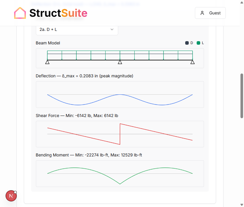
Figure. Two-span continuous glulam over three supports with uniform load on both spans; negative bending at the interior support and positive bending in the span regions—Fbx+ vs Fbx− per Supplement Table 5A. Diagrams generated in StructSuite as described above.
Why this geometry matters in practice: Specifiers often choose continuous girders to reduce depth or meet deflection limits compared with simple spans. The penalty is a larger negative moment at the interior column than the positive moment in the span, and often a lower tabulated Fbx− than Fbx+, so the hogging zone frequently governs bending even when compression-edge bracing is adequate.
2. Elastic internal forces (StructSuite beam solver, 2a. D + L)
For this prismatic two-span beam with equal spans L = 18 ft and uniform w = 550 lb/ft on the full length (D + L service loads combined for the strength / service diagrams), StructSuite’s elastic line analysis gives the ordinates below (visualization combination 2a. D + L). Reactions match the usual continuous-beam closed forms; peak sagging moment is the maximum M+ along the span (9wL²/128 for equal two-span UDL), not the wL²/16 value at midspan.
| Quantity | Source | Value |
|---|---|---|
| Peak sagging moment M+ (governing Fbx+ check) | StructSuite M diagram (max positive) | 12,529 lb-ft = 150,348 lb-in |
| Hogging moment M− at interior support | StructSuite M diagram (min) | −22,274 lb-ft = −267,288 lb-in (≈ −wL²/8) |
| Shear V (magnitude at interior support, governing shear check) | StructSuite V diagram | 6,142 lb (cf. 5wL/8 = 6,188 lb from closed form) |
| End reaction (each exterior bearing) | Statics / 3wL/8 | 3,713 lb |
| Interior reaction (column) | Statics / 5wL/4 | 12,375 lb |
Note: Midspan sagging moment wL²/16 = 11,138 lb-ft is lower than the true peak 12,529 lb-ft; use 12,529 lb-ft for stress at the critical sagging section.
3. Section properties (gross section)
b = 5.125 in., d = 15.0 in.
S = bd2/6 = 5.125 × 225 / 6 = **192.2 in.3**
I = bd3/12; **d**3 = 3,375 in.3; **I** = 5.125 × 3,375 / 12 = **1,441.4 in.4**
Rounding in this note: S and I use one decimal in.³ / in.⁴; bending stresses to whole psi unless a tighter value is needed for the comparison; deflection to two decimal places of an inch in summaries. Use full precision on contract calculations.
4. Reference design values (Supplement Table 5A)
Table 5A (bending members) for 24F-1.8E (values consistent with the NDS Supplement):
| Symbol | Role in this problem | Value (psi) |
|---|---|---|
| Fbx+ | Positive-moment regions (bottom in tension) | 2,400 |
| Fbx− | Negative-moment regions (top in tension) | 1,450 |
| Fvx | Shear | 265 |
| E | Deflection | 1.8 × 10⁶ |
| Emin | Stability / buckling uses (not used for δ below) | Per Table 5A |
Key point: Fbx− is not a “reduced Fb for the same fiber”; it is the reference stress for the stress state associated with negative bending about the strong axis. Apply the same C factors (with CL and CV rules) to each reference value to obtain F′b+ and F′b−.
5. Adjustment factors (ASD)
CD: D + L with floor live controlling duration → CD = 1.0 (NDS load duration table; shortest-duration load in the combination).
CM, Ct: Dry service, T ≤ 100 °F → 1.0 for strength and E (unless project-specific otherwise).
Cfu, Ci, Cr: Strong-axis bending, single girder → Cfu = 1.0, Ci = 1.0, Cr = 1.0 per NDS applicability.
CL: Required for both positive and negative moment regions. Positive zones: compression on top—often fully braced by floor sheathing. Negative zone at interior support: compression on bottom—often not braced the same way; unbraced length lu between points of lateral support to the compression edge must be used in NDS 5.3.4. This example assumes CL = 1.0 in both zones for illustration after the engineer verifies bracing; if CL < 1.0 in the hogging region, recalculate F′b−—that often controls continuous glulam design.
CV (NDS 5.3.6, Equation 5.3-1): Use span length L = 18 ft (each span), d = 15 in., b = 5.125 in., x = 10 (Douglas Fir–Larch, not Southern Pine):
CV = (21/18)0.1 × (12/15)0.1 × 1 ≈ **0.993**
CV vs CL for glulam Fbx: CV is computed per NDS 5.3.6 (Equation 5.3-1). CL is computed per NDS 5.3.4 / 5.3.5 (beam stability). These are different phenomena; do not assume one formula applies to the other. For structural glued laminated timber reference bending design values from Supplement Table 5A, the Supplement states that CV shall not be applied simultaneously with CL—use the lesser of CV and CL in the Fbx adjustment path (verify the exact sentence in your NDS/Supplement edition). Sawn dimension lumber uses size factor CF, not CV; the Table 5A CV/CL rule is glulam-specific.
6. Flexure — positive moment region (sagging, Fbx+)
Bending stress magnitude (M+ = 150,348 lb-in from Section 2):
fb+ = M+ / S = 150,348 / 192.2 ≈ **782 psi**
Adjusted allowable (same factor product applied to Fbx+; min(CL, CV) = min(1.0, 0.993) = 0.993):
F′b+ ≈ 2,400 × 1.0 × 1.0 × 1.0 × 0.993 × 1.0 × 1.0 × 1.0 × 1.0 ≈ **2,380 psi**
Check: 782 psi ≤ 2,380 psi → OK (positive zone is not governing here).
7. Flexure — negative moment region (hogging, Fbx−) — usually governing
Bending stress magnitude at interior support (|M−| = 267,288 lb-in from Section 2):
fb− = \| M− \| / S = 267,288 / 192.2 ≈ **1,391 psi**
Adjusted allowable (apply adjustments to Fbx−; min(CL, CV) = 0.993):
F′b− ≈ 1,450 × 1.0 × 1.0 × 1.0 × 0.993 × 1.0 × 1.0 × 1.0 × 1.0 ≈ **1,440 psi**
Check: 1,391 psi ≤ 1,440 psi → OK for this trial section if CL = 1.0 in the hogging region.
7.1 Beam stability at interior support — sensitivity (why CL = 1.0 is often too optimistic)
At the interior support, hogging puts compression in the bottom of the beam. Floor sheathing on the top does not brace that compression edge. Unless strapping, ties, ceiling, blocking, or column details provide lateral support to the bottom flange near the support, CL can be well below 1.0 and often governs continuous glulam design. The baseline calculation above passes only because fb− ≈ 1,391 psi is barely below F′b− ≈ 1,440 psi (demand is ~97% of capacity).
Using the same Fbx− adjustment path as Section 7 with min(CL, CV) and CV = 0.993 fixed, F′b− ≈ 1,450 × min(CL, 0.993) psi (other factors 1.0):
| Assumed CL at hogging region | min(CL, 0.993) | F′b− (approx.) | 1,391 psi check |
|---|---|---|---|
| 1.0 (illustration only) | 0.993 | ~1,440 | OK |
| 0.90 | 0.90 | ~1,305 | NOT OK |
| 0.85 | 0.85 | ~1,233 | NOT OK |
To just satisfy fb− ≤ F′b− with fb− = 1,391 psi and Fbx− = 1,450 psi, you need min(CL, CV) ≥ 1,391 / 1,450 ≈ 0.96 (so CL ≥ ~0.96 when CV controls at 0.993). Calculate CL from NDS 5.3.4 using the actual lu, le, and Cb for the hogging segment—do not copy CL from the positive-moment zones.
Engineering takeaway: The ratio of demand to capacity is much higher here than in the positive zone (~0.97 vs ~0.33 on stress basis for this set of numbers). In practice, continuous glulam often sizes from Fbx− or from deflection or from CL at the interior support.
8. Shear (maximum considered here — interior support)
For a rectangular section, NDS 3.4.2 is used in many wood design workflows in the form Vn = (2/3) F′v A with A = bd, or equivalently compare 1.5V/A to F′v. With V = 6,142 lb from Section 2, b = 5.125 in., d = 15 in.:
fv = 3V / (2bd) = 3 × 6,142 / (2 × 5.125 × 15) ≈ **120 psi**
fv = 1.5V / A with A = bd = 76.875 in.2 → 1.5 × 6,142 / 76.875 ≈ **120 psi**
F′v = Fvx × CD × CM × Ct × Ci × Cvr = 265 psi (dry, Cvr = 1.0 without notches).
Check: 120 psi ≤ 265 psi → OK.
8.1 Bearing and tension perpendicular to grain (qualitative)
Strong-axis bending puts extreme-fiber tension and compression parallel to grain along the beam length; the Fbx+ / Fbx− checks above address that. Separately, supports and connections can introduce compression perpendicular to grain (Fc⊥, bearing per NDS bearing provisions) and, for some details, tension or splitting perpendicular to grain (e.g. concentrated reactions, hangers, notches, or fastener groups). Wood is relatively weak in tension perpendicular to grain; check tension perpendicular to grain at supports and connections where applicable to the load path and detailing, per NDS and manufacturer data. This hand example does not size bearing length, hardware, or connection capacities.
9. Deflection (serviceability — elastic δ from StructSuite)
For serviceability, compare immediate elastic deflection from the same E′I model as the analysis. StructSuite reports peak magnitude δ for the selected visualization case; for 2a. D + L (total w = 550 plf on both spans), δmax = 0.2083 in. (peak magnitude along the span; E′ = E × CM × Ct × Ci for stiffness, E′ ≈ E here).
δD+L = **0.2083 in.**
Live-load-only deflection for the same beam and supports scales linearly with load intensity in elastic range: δL ≈ δD+L × (wL / w) = 0.2083 × (330 / 550) ≈ 0.125 in.
δL ≈ **0.125 in.**
Compare to IBC Table 1604.3 limits (e.g. L/360 for live on floors with flexible finishes): L/360 = 216/360 = 0.60 in. → OK for δL vs L/360.
Long-term deflection (creep): The elastic δ above is immediate. Sustained loads cause creep; total deflection over time can exceed these values. Confirm NDS, IBC, and project rules for creep factors or stricter serviceability criteria where applicable.
10. Governing summary (this example)
| Limit state | Controlling region | Demand vs capacity | Result |
|---|---|---|---|
| Flexure + | Peak sagging (line analysis) | fb+ ≈ 782 psi vs F′b+ ≈ 2,380 psi | OK |
| Flexure − | Interior support | fb− ≈ 1,391 psi vs F′b− ≈ 1,440 psi | OK (tight; verify CL) |
| Shear | Interior support | fv ≈ 120 psi vs F′v = 265 psi | OK |
| Deflection (live) | Exterior span | δL ≈ 0.125 in. vs L/360 = 0.60 in. | OK (elastic δ from Section 9) |
11. Relation to analysis software and StructSuite
Any tool you use should: (1) produce M+ and M− for continuous framing; (2) apply Fbx+ and Fbx− in the correct regions; (3) apply CV (5.3.6) and CL (5.3.4/5.3.5) per NDS, and for glulam Table 5A follow the Supplement rule that CV and CL are not used together—use the lesser where that provision applies. StructSuite’s framing verification path for glulam uses Supplement Table 5A for Fbx+/Fbx− and computes CV from NDS Equation 5.3-1; continuous beam moments and shears come from the beam solver for the loads you enter.
12. References (NDS 2024 and Supplement)
- NDS 2024 Chapter 4 — Load duration (CD).
- NDS 2024 Chapter 5 — ASD adjustments; Equation 5.3-1 (CV); beam stability (CL).
- NDS Supplement Table 5A — Fbx+, Fbx−, Fvx, E, Emin.
- IBC — Deflection limits; live load.
- Elastic continuous-beam theory — line analysis for moments/shear/deflection; peak M+ for equal two-span UDL is 9wL²/128 (not wL²/16 at midspan).
This technical note is educational. Confirm bracing, CL, reference stresses from the Supplement edition in use, reactions, connections, and deflection criteria with the governing NDS, IBC, and the authority having jurisdiction.